


|
|
 |
 |
 |
|
|

Antentop is FREE e-magazine devoted to Antennas and Amateur Radio an
Special page devoted to
RF Sniffer

Custom Search
|
ANTENTOP- 01- 2018 # 022 |
RF
Sniffer |
|
|
|
|
Again E- Bay was the source of the diodes. I found
there 50 each excellent UHF TOSHIBA 1SS315 type diodes for 5 USD
shipping included. It was small SMT parts but in recent times
almost every electronic part comes in SMT package. Table 1 shows main parameters for the diode. Forward
voltage for the diode is only 0.25 V (Forward voltage for Silicone
diode is 0.7 V, for germanium is 0.3 V), so the diode could catch
low level RF voltages that would be present on the antenna- inductor
L1. Total capacitance for the diode is 0.6 pF, so the diode may
work in my FSM on frequencies up to 3-GHz. |
1N35. Made
in USA, SYLVANIA |
|
Table 1 Electrical Characteristics of 1SS315
|
|
|
1SS315 diode showed very good result during my experiments.
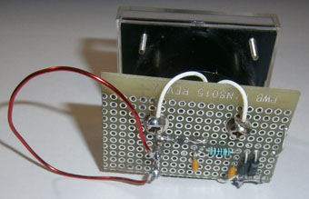
After that I made finished design of the device. But... the finished
design means a breadboard PCB attached to the internal contact
screw of the 100- micro- ampere meter. Newer any cabinet there
was around. Such design allows me do different experiments with
the RF Sniffer. I changed length of L1 (length of wire of the
L1 should be equal to wavelength of the signal to be catch) for
different frequencies, I may remove board with loop antenna from
the meter and place antenna in some hard accessed places to catch
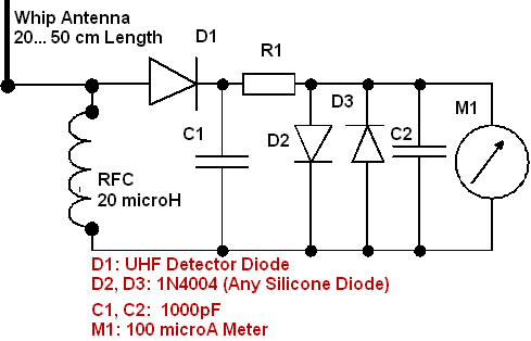
RF. I install RF choke with whip antenna instead of L1 to turn
the device to sniff HF (1.8- 50.0- MHz) and VHF- UHF (145 and
430- MHz). Figure 2
shows modified RF Sniffer.
RF Sniffer: Front View |
Figure 2 Modified RF Sniffer
RF Sniffer: Rear View |
|
|
|
|
|
Page- 88 |


 |
 |
|
 |
|
|
|||
Just for Fun:

Powered byIP2Location.com
Thanks for your time!
Last Updated:
January 3, 2020 21:19