


|
|
 |
 |
 |
|
|

Antentop is FREE e-magazine devoted to Antennas and Amateur Radio an
Special page devoted to
Antenna Switching Units

Custom Search
|
ANTENTOP- 01- 2018 # 022 |
Antenna
Switching Units |
|
|
|
|
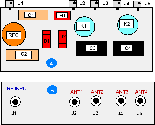
How it works: RF voltage for antenna and
control voltage for RF relays are going through one coaxial cable.
The RF and Control voltages are separated at input and output of
the coaxial cable with help of RF chokes. Inside the unit A1 installed
main transformer that provides supply voltage for RF-relays. Logical
for the code/decode circuit is very simple. If supply voltage is
not coming to the coaxial cable then antenna # 1 is switched on.
If the voltage in negative polarity (relative to the braid of the
coaxial cable) is going to the coaxial cable then relay K1 powered
up and it is switched on antenna # 3. If the voltage in positive
polarity (relative to the braid of the coaxial cable) is going to
the cable then relay K2 powered up and it is switched on antenna
# 2. If the AC is going to the cable then both relay K1 and K2 powered
up and there is switched on antenna # 4.
|
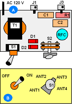
Figure
14 Design of Unit
A1 |
|
|
|
|
Figure
15 Design of Unit
A2 |
|
|
|
|
|
|
Page- 86 |
 |
 |
|
 |
|
|
|||
Just for Fun:

Powered byIP2Location.com
Thanks for your time!
Last Updated:
June 24, 2018 18:14