
Antentop is FREE e-magazine devoted to Antennas and Amateur Radio an
Special page devoted to
Delta Antenna for 80- 10 meter Band

Custom Search
|
ANTENTOP- 01- 2018 # 022 |
Delta Antenna for 80- 10 meter
Band |
|
|
|
|
Delta Antenna for 80- 10 meter Band |
|
|
|
|
|
|
Serge Smirnov,
RK3BJ, ex: EW7SF, UC2SF |
|
|
|
|
The
simplest antenna that could provide operation on all HF bands
is a Delta Antenna. The antenna made in the shape of Delta needs
minimum points for installation, does not required grounding like
a vertical does and the antenna is not critical to nearest objects.
The antenna does not required high mast for installation. If the
antenna made as one band one it may feed direct through a coaxial
cable. However for multiband operation the antenna is required
a matching device at its feed-points. For a long time I use to a Delta Antenna for 80- meter
(perimeter is 84 meters) on amateurs bands from 80 to 10 meters.
Two upper points of the antenna are fixed at the roof of a five-storey building third point (feed-points of the
antenna) is fixed on the balcony on the third floor. Wires
from the feed- points are going into my shack and connected to
an ATU. The ATU may be connected to transceiver by coaxial cable
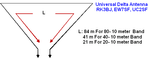
of any length. Figure 1
shows design of the delta antenna. Figure 2 shows schematic of the ATU. |
ATU consists of a broad band balanced RF transformer
T1 and Pi circuit that match antenna impedance to impedance of
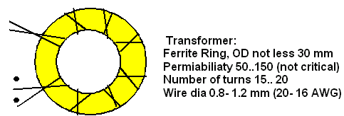
the feeding coaxial cable. Figure 3 shows design of the balanced transformer. The transformer
may be connected to the antenna and to matching circuit according
to variant 1 or variant 2. It is depends on antenna placement
(so on to antenna impedance on the bands) and to parameters of
the transformer. Practice shows best variant for your antenna
installation.
|
|
Figure 1 Design of the Delta Antenna
Figure 3 Design of the Balanced Transformer |
|
|
Page- 12 |
|
12 13
 |
 |
|
 |
|
|
|||
Just for Fun:

Powered byIP2Location.com
Thanks for your time!
Last Updated:
January 1, 2020 23:15


