antentopSince2 July

** PLEASE DESCRIBE THIS IMAGE **


Antentop is FREE e-magazine devoted to Antennas and Amateur Radio an

Special page devoted to

Practical Balcony Version of an Old Military Car Antenna

Custom Search


ANTENTOP- 01- 2017 # 021

Practical Balcony Version of an Old Military Car Antenna


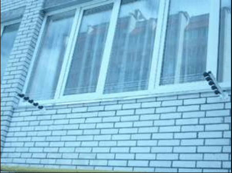
The antenna was installed outside of my balcony in the second floor. The antenna really served as Clothes Dryer so nobody knows about its real application.

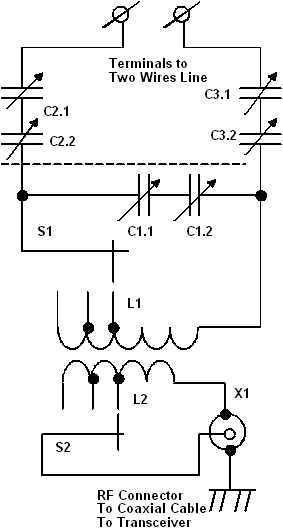
 Antenna was fed through an ATU. Figure 2 shows schematic of the ATU. Schematic of the ATU is close to a military ATU that used with such type of antennas. Capacitors C1, C2 and C3 were air dielectric from old tube receivers.

 The capacitors were 12- 495- pF each. All capacitors were installed on isolation plates. Only stator plates were used in the capacitors for connection to ATU. C1 was rotate through a plastic shaft. Capacitors C2 and C3 were tied through isolation shaft that provided its synchronous rotation.

 Inductor L1 was tuned to resonance with the transmitting frequency. L1 has 20 turns Taps made from the hot end then from 15 and 10 turns (from the cold end). The inductor was wound by copper wire in 1.2- mm diameter (17-AWG) on form in diameter of 50- mm, gap between turn is 3.5- mm.

 Inductor L2 helps match the ATU with transceiver output. The inductor has 5 turns of copper wire in diameter of 2.2- mm (11- AWG). The inductor is wound in the center of L1. Taps made from the hot end then from 4 and 3 turns (from the cold end). With the ATU antenna could be tuned from 1.8 to 14.5- MHz. I is possible tune the antenna up to 30- MHz if change L1 and L2 to appropriative ones.


Figure 2

ATU for the Balcony Version of an Old Military Car Antenna


Two wires Line should not exceed 2... 2.5 meter length. It was the length from the antenna to the ATU that was installed on the windowsill at the window apart of the antenna.

 Original ATU contained two RF- Current meters that was installed in the wires of the Two Wires Line. I nave not the devices so for tuning of the antenna I used to usual Fluorescent Light Tube Bulb that was installed near feeding points of the antenna. Antenna was tuned to maxima lighting of the bulb.

 Antenna had wide passband. It was need not retune the antenna inside of the band being tuned on it. I used near 40- 50 W with the antenna. No TVI was observed.

 73! ex UA9LBG

 Reference 1:


Old Military HF - Antennas of Communication Cars

http://www.antentop.org/004/oma.htm


Balcony Clothes Dryer in the Russia


www.antentop.org

Page- 56


55 56


Just for Fun:

Map IP Address
Powered byIP2Location.com

Thanks for your time!

Last Updated:

January 4, 2020 14:18

** PLEASE DESCRIBE THIS IMAGE **

** PLEASE DESCRIBE THIS IMAGE **

2003entop