

Antentop is FREE e-magazine devoted to Antennas and Amateur Radio an
Special page devoted to
Experimenters
with
Non Snap Ferrite Cylinder
Bead RF Chokes

Custom Search
|
ANTENTOP- 01- 2016 # 020 |
Experimenters with Non Snap Ferrite Cylinder Bead RF
Chokes |
|||||||||||||||||||||||||||||||||||||||||
|
|
|
|||||||||||||||||||||||||||||||||||||||||
|
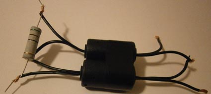
Second experimental transformer was made with two Cylinder Ferrite RF Chokes.
Figure 6
shows schematic of the transformer. It was classical RF Transformer
where one turn is primary and second turn is the secondary winding.
Then the transformer was tested. Primary winding was connected
to MFJ- 259B. Secondary winding was loaded on to 51- Ohm resistor.
Figure 7 shows the transformer loaded
to 51-Ohm resistor. Table 2 shows data obtained for the two Ferrite
RF Chokes transformer. As you can see from the table the transformer had parameters
better the one cylinder transformer. Certainly the transformer
may be used for receiving purposes. I tested the transformer with
my transceiver IC- 718 and receiver Hallicrafters
S- 85. Transformer worked good up to 80- meter Band. Then I observed
some dropping of receiving signals. However I could compensate
it with adding RF- gain at transceiver and receiver where the
transformer successfully worked at MW-Band. Transformer was tested
with IC-718 in transmitting mode, 15- wt. SWR showed by IC- 718
is close to SWR showed by MFJ- 259B. |
Figure 7 RF Transformer on Two Cylinder Ferrite RF Chokes loaded
to 51- Ohm Resistor Conclusion: The transformer may be used as Insulated Transformer for Receiver at the
HF and MW. The transformer may be used for some purposes (like
insulation transformer installed on antenna and then matched with
coaxial cable) at transmission mode at the 40- 10 meter Bands.
|
|||||||||||||||||||||||||||||||||||||||||
|
Figure 6 RF Schematic for RF Transformer Made on Two Cylinder Ferrite
RF Chokes |
||||||||||||||||||||||||||||||||||||||||||
|
|
|
|||||||||||||||||||||||||||||||||||||||||
|
Table 2 Two Cylinder Ferrite RF Chokes loaded to 51- Ohm Resistor. Data obtained
with MFJ- 259B and IC-718
|
||||||||||||||||||||||||||||||||||||||||||
|
|
||||||||||||||||||||||||||||||||||||||||||
|
Page- 78 |
||||||||||||||||||||||||||||||||||||||||||
 |
 |
|
 |
Just for Fun:

Powered byIP2Location.com
Thanks for your time!
Last Updated:
January 4, 2020 22:15


