

|
|
 |
 |
 |
|
|
Antentop is FREE e-magazine devoted to Antennas and Amateur Radio an
Special page devoted to
Broadband Transformer 50/200 Ohm

Custom Search
|
ANTENTOP- 01- 2015 # 019 |
Broadband Transformer 50/200 Ohm |
|
|
|
|
|
|
|
|
|
|
|
By: Sergey Popov, RZ9CJ, Ekaterinburg, Russia Credit Line:
http://qrz-e.ru/forum/29-786-2 |
|
|
|
|
Below
I describe a simple way to make broadband transformer 50/200 Ohm
with isolated windings. (Theoretically the transformer is for
50/140- Ohm. However it works fine for most common using 50/200
Ohm.) Figure 1 shows schematic of the transformer. At
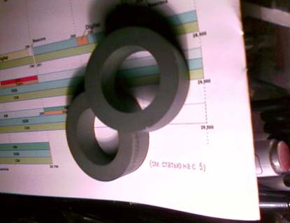
first you need take a ferrite ring (or several identical ferrite
rings) with permeability 600- 2000. OD should be 40- 50- mm. Power
going through the transformer depends on the sizes. I took two
ferrite rings with permeability 2000 for the transformer. Figure 2 shows the rings. The
rings stuck together. Rings should be protected from atmospheric
influences. It may be done with protection lacquer or just with
electrical insulation tape. Figure
3 shows two rings wrapped with electrical insulation
tape. Of course, at the antenna the transformer should be protected
from straight atmospheric influences with help of a simple cover.
|
Figure
1 Schematic of the
Broadband Transformer 50/200 Ohm Second
winding has two turns around each turn of the first winding. Wires
should be close and parallel each to other. Figure 6 shows beginning of
the second winding at one side of the ring. In one turn (first
winding) is in brown, two turns (second winding) are in yellow.
Figure 7 shows ready second winding. |
|
Figure
2 Rings for the Broadband
Transformer |
Figure
3 Two Rings Wrapped
with Electrical Insulation Tape |
|
I used
thin wire in diameter near 1.5- mm (14- AWG) for the windings.
First winding contains 2 turns. Figure 4 shows transformer with the winding. Then
one turns is moved to the opposite side of the ring. It is the
first winding. Figure
5 shows the first winding. |
First
winding is for coaxial cable 50 Ohm the second one for antenna
200 Ohm. After that it is pressed the turns together and fixed
it with electrical insulation tape. Transformer 50/200 Ohm is
ready. Figure 8 shows the transformer. |
|
|
Page- 96 |

96 97
 |
 |
|
 |
Just for Fun:

Powered byIP2Location.com
Thanks for your time!
Last Updated:
January 5, 2020 20:10