|
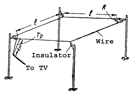
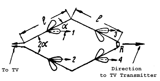
Table 1 shows data for Rhombic
Antenna with different parameters. To keep such parameters antenna
should be placed above the ground at height not less the 2- 3
wavelength of the working band of the antenna.
Antenna may be fed by open ladder line with wave impedance 300- 600-
Ohm. At this case the antenna could be matched at all working
frequencies band. Antenna may be fed through a coaxial cable when
two simple matching transformers are used. Figure 3 shows feeding Rhombic Antenna through
a coaxial cable. First transformer is a broadband transformer
made on two wire ladder line. It is two wires line with varying
wave impedance on the length.
|
The wave impedance
of the line changes from 700- Ohm at rhomb side to 300- Ohm at
coaxial cable side.At coaxial cable side the coaxial cable should not connect straight away
to the line. Coaxial cable connected to the line through a symmetrical
transformer 4:1 made on lengths of the used coaxial cable. The
transformer makes symmetrical and provides matching of the Rhombic
Antenna to coaxial cable. Loop of the coaxial cable should have
electrical length lambda/2. To calculate such transformer you
need to know the shortening coefficient of the used coaxial cable.
|


