

|
|
 |
 |
 |
|
|
Antentop is FREE e-magazine devoted to Antennas and Amateur Radio an
Special page devoted to
R3PIN Experimenters with UA6AGW Antenna

Custom Search
|
ANTENTOP- 01- 2015 # 019 |
R3PIN Experimenters with UA6AGW Antenna |
|
|
|
|
Figure 3 Coupling Loop at UA6AGW Antenna Data for the Antenna Dimension of the antenna were too big for the 2- meter
band. Antenna with help of C1 and C2 may be tuned across 18- 56-
MHz. Test of the antenna was made at 10- meter band at frequency
28.850- MHz. Antenna was tested at position
showed at Figure 1. Antenna had SWR 1.0: 1.0. C2 had maximum
capacitance. Antenna was tuned to the 28.850- MHz by C1. |
Figure 4 Whiskers and Capacitors |
|
Antenna had Diagram Directivity similar to classical
UA6AGW Antenna, i.e. the DD was ellipse sitting along whiskers
of the antenna. Side suppression of the antenna was near minus15-
dB. It was possible to make local QSOs when the antenna was placed
at a table or windowsill. Experimenters with the antenna was loaded
to Youtube at: http://www.youtube.com/watch?v=-uNrlRNcLu4&feature=em-upload_owner Experiment # 2 Design
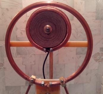
of the Antenna Second antenna made by R3PIN is
shown at Figure
5.The antenna was made as a table design. Dimensions
of the antenna were decreased compare to antenna from first experiment.
Loop of the antenna has diameter 5.5- cm. It was a copper tube
in 4.7- mm OD. To make a "copper tube coaxial cable"
inside of the tube was inserted Teflon insulated wire in 0.27-
mm diameter. Whiskers of the antenna had length 10- cm. |
The whiskers made from strand
tinned wire. Capacitors C1 and C2 were ceramic dielectric with
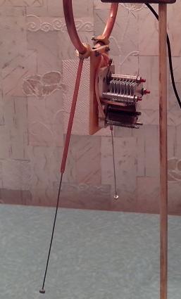
capacitance 6- 25- pF. Coupling loop was completely different from the counterpoint
of antenna shown at Figure 2. The coupling loop was placed athwart
to radiation loop. Coupling loop had two turns of copper wire
in 1.2- mm diameter (17-AWG). Gap between the turns was 5- mm.
Coaxial cable was soldered directly to the coupling loop. Two ferrite rings, one at the
coupling loop another one at the connector side of the cable,
were placed on to the coaxial cable. Figure 6 shows the coupling loop. With help a
fixture (similar to the clock hand) the loop could move along
the radiation loop. Figure
7 shows the fixture. |
|
|
|
|
|
|
|
|
|
|
|
Page- 51 |
 |
 |
|
 |
Just for Fun:

Powered byIP2Location.com
Thanks for your time!
Last Updated:
January 5, 2020 16:19