

Antentop is FREE e-magazine devoted to Antennas and Amateur Radio an
Special page devoted to
Pocket Antenna Tuner

Custom Search
|
ANTENTOP- 01- 2014 # 018 |
Pocket Antenna
Tuner |
|
|
|
|
Antenna
and transmitter sockets (to decrease the sizes of the box) did
not use at the design. SWR- meter (or RF- Meter) as well did not
used here for the reason. Variable tank capacitor had simple inbuilt
vernier 1:3. The tuner could match antenna
impedance up to 300-Ohm. Limitation is only to working voltage
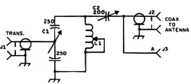
of the row capacitors and input variable capacitor. Figure 2 shows (for reference) schematic of the Lew McCoy's
"Ultimate Transmatch." |
Note from I.G.: The Ultimate Transmatch
was described in the "Beginner and Novice" section of
the July 1970 QST (Page 24). The circuit was very popular that
it was also published in several of the ARRL Handbook from the
1970s. I have seen one "Real McCoy Transmatch" (as a seller sad to me) at one of Ontario
Hamfests. When I decided if I heed to buy this one or not,
another person bought it. |
|
Figure 2 "Ultimate Transmatch" by Lew McCoy, W1ICP |
|
|
|
|
|
Simple
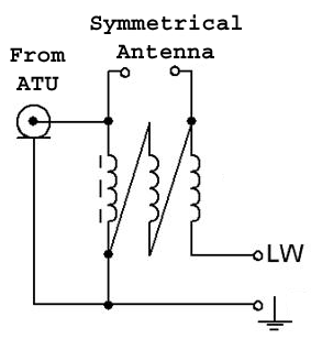
broadband transformer, connected to the tuner, allows use the
tuner with symmetrical antennas fed through ladder line and with
generation of the wire antennas. The transformer provides 1:4
and 1:9 transformation ratio.
Figure 3 Broadband Transformer |
Lew McCoy, W1ICP Figure 3 shows schematic of
the transformer. Transformer is wound on to ferrite ring in 30-
mm OD and permeability 20 by triple wires in diameter 1- mm (18-AWG)
in Teflon insulation. Pictures show design of the tuner. |
|
|
|
|
Page- 91 |
|
 |
 |
|
 |
Just for Fun:

Powered byIP2Location.com
Thanks for your time!
Last Updated:
January 7, 2020 22:43


