

Antentop is FREE e-magazine devoted to Antennas and Amateur Radio an
Special page devoted to
Regenerative Receiver BARABASHKA-3

Custom Search
|
ANTENTOP- 01- 2013 # 017 |
Regenerative Receiver BARABASHKA-3 |
|
|
|
|
The receiver consumes near
10- milliampere. Inductors L1 and L2
are coiled by an enamel wire in diameter 0.2- 0.25- mm (30- 32-
AWG) on the plastic form (it was used a surplus form from an old
receiver) in 5- mm diameter. The inductor is trimmed by a small
ferrite rod to needed band. It is possible to use the inductor
without a trimming rod. Trimmer capacitors C4 and C7 are used
to change the border of the bands. Inductor L1 has 9 turns. Inductor
L2 has 14 turns. |
The regenerative receiver
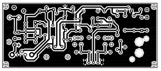
made on one sided PCB plate by sizes 120 x 50- mm. Figure
2 shows the PCB of the receiver.
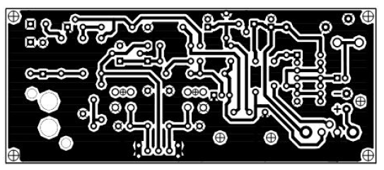
It is view on the printed lay. Figure 3 shows the view on the PCB at the "mirror view"
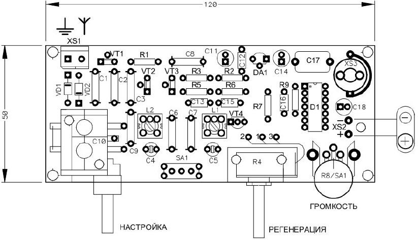
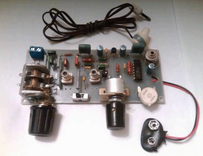
(view from the side of the parts). Figure 4 shows PCB with installed parts on it. Figure
5 shows the picture of the
Regenerative Receiver. |
|
Figure 2 PCB of the Regenerative Receiver |
Figure 3 PCB of the Regenerative Receiver in the "Mirror View" |
|
Figure 4 PCB of the Regenerative Receiver with Installed Parts on It |
|
|
Figure 5 Picture of the Regenerative Receiver |
If you are interested to get a kit for the receiver (the kit may
include the PCB, all parts + coiled inductors, variable capacitor,
headphones), please, contact directly to Rinat
via his mail: radiorinat at mail.ru. |
|
Page- 84 |
|
83 84
 |
 |
|
 |
Just for Fun:

Powered byIP2Location.com
Thanks for your time!
Last Updated:
January 9, 2020 22:44


