


|
|
 |
 |
 |
|
|
Antentop is FREE e-magazine devoted to Antennas and Amateur Radio an
Special page devoted to
Ferrite Magnetic Antenna for the 160, 80 and 40- meter Bands

Custom Search
|
ANTENTOP- 01- 2013 # 017 |
Ferrite
Magnetic Antenna for the 160, 80 and 40- meter Bands |
|
|
|
|
|
Vladimir
Fursenko, UA6CA Ashot Bazoyan, UA6ACA
Credit Line: www.cqham.ru |
|
|
|
|
The
experimental antenna made on so called home made "Ferrite
Linear Heterogeneous Rod." It is an anisotropic ferrite rod.
This one has advantages before isotropic ferrite rod. Heterogeneous
Rod does not require special high efficiency ferrite stuff. The "thick"
areas are magnetic concentrator. |
Combination of the thin and thick areas in the Ferrite Linear Heterogeneous
Rod allows significantly improved
the efficiency of the ferrite antenna. Using of the Heterogeneous Rod
allows create a ferrite antenna for 160- 40- meter. Figure 1 shows design of the antenna. |
|
Figure
1 Design of the Ferrite Magnetic Antenna for the 160,
80 and 40- meter Bands |
|
|
For
the construction of the antenna there is required 1- e.a.
ferrite rod with mu= 150 and 14- e.a.
ferrite rods with mu= 400. All rods have length 200- mm and the
diameter 10- mm. Ferrite rod mu= 150 is glued with the ferrite
rods mu= 400 through dielectric washers (2- mm thickness, plexiglass).
Then the 3 ferrite rods (mu= 400 + mu= 150 + mu= 400) covered
by a Scotch in a several lays. Summary thick of the cover should
be 0.5... 1.0- mm. Ferrite
rods of the magnetic concentrator are fastened to the 3- rod ferrite
by the Scotch. Inductors L1 and L2 are coiled in one direction
by enamel wire in diameter of 0.3- mm (28- AWG). Inductor L1 contains
9- turns. Inductor L2 contains 65- turns. Taps are made of 15,
25, 40 and 50- turns. Data for the L1 and L2 may be differed when
different of the described ferrites are used. |
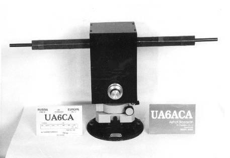
Figure 2 Ferrite Magnetic
Antenna on the Revolving Stand Antenna is mounted on a revolving stand from an old
theodolite. Figure
2 shows the assembled antenna on the stand. |
|
|
Page- 73 |
73
 |
 |
|
 |
Just for Fun:

Powered byIP2Location.com
Thanks for your time!
Last Updated:
January 8, 2020 22:41