


|
|
 |
 |
 |
|
|
Antentop is FREE e-magazine devoted to Antennas and Amateur Radio an
Special page devoted to
Ferrite Magnetic Antenna for the 160 and 80- meter Bands

Custom Search
|
ANTENTOP- 01- 2013 # 017 |
Ferrite Magnetic Antenna for the 160 and 80- meter Bands |
||
|
|
|||
|
|
|
||
|
|
Vladimir Fursenko, UA6CA and Ashot Bazoyan, UA6ACA Credit Line: www.cqham.ru |
||
|
The Ferrite Magnet Antenna for
the 160 and 80- meter Bands is just an experimental prototype.
It was done to give some thought and ways for those hams who would
like to research the type of antennas. |
The advantage of the ferrite magnet
antenna is the small sizes. The antenna could be easy protected
from the atmospheric influence while this one being installed
outside of a room. |
||
|
Figure
1 Schematic and Design
of the Ferrite Magnet Antenna for the
160 and 80- meter Bands |
|||
|
Ferrite
Body of the antenna made of 20 ferrite rods. It was used rods
with mu= 400, length = 200- mm and diameter = 10- mm. The rods
were installed in ring similar to a stator of an electric motor.
Diameter of the ring was 90- mm. The rods were installed with
step in 18- degree. Copper wire in diameter 1- mm (18- AWG) was
used for the antenna inductors. It was no gap between coils of
the inductors. Inductor
L1 has 2 x 8 turns. Inductor L2 has 2 x 2 turns. All inductors
are coiled in one direction. Left and Right parts of the inductor
L2 connected symmetrically to the inductor L1. Capacitor C2 provides
matching with the transceiver. (I. G.: I made the antenna
some years ago. I recommend use a variable capacitor- 3 x 12x495-
pF instead of the fixed one C2.) Antenna may stand
RF- Power up to 10- Wtts. Capacitor
C1 should have air gap for transmitting variant of the antenna. The Ferrite Magnet Antenna (at the testing in the Air)
worked good from 1750- kHz to 3660-kHz. Efficiency of the antenna
was low at the frequencies higher the 3700- kHz. |
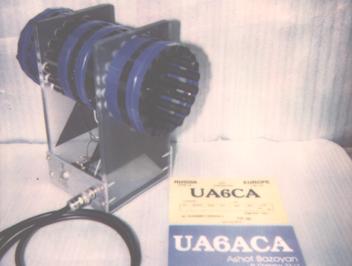
Figure 2 Picture of the Ferrite Magnet Antenna for the 160
and 80- meter Bands |
||
|
|
Page- 43 |
||
43
 |
 |
|
 |
Just for Fun:

Powered byIP2Location.com
Thanks for your time!
Last Updated:
January 8, 2020 22:12