


|
|
 |
 |
 |
|
|
Antentop is FREE e-magazine devoted to Antennas and Amateur Radio an
Special page devoted to
Super Broad Band HF- VHF Antenna

Custom Search
|
ANTENTOP- 01- 2011, # 015 |
Super Broad Band HF- VHF
Antenna |
|
|
|
|
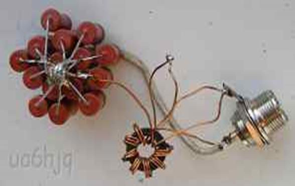
Figure 6 Design of the RF transformer 1:9 |
|
|
At the
design of the wide band antenna an RF voltage through RF up- transformer
1:9 is going to the antenna. So efficiency of the antenna would
be better (in theory) compare to the antenna from the Figure 2 because RF- voltage across of the antenna
wire should be higher compare to the simple wide band antenna.
RF Transformer is wound by three wires twisted together. The winding
is placed evenly around the ferrite core. For my ferrite ring
I got best result with 5 turns around the ferrite core. Dummy
Load for the antenna was made with 15 resistors of 6.8- kOhm/2-
Watts that were bridged together. The load could stand up to 100-
Watts CW/SSB for 15- minutes. Note from I.G.: There are some limitations that could turn antenna from the Figure 5 to losing antenna compared to Figure 2. |
SWR of
the antenna from Figure 5 was almost 1.0:1.0 at the band from 1.8
to 14 MHz, then evenly increase to 2.0:1.0
at 28- MHz band. The antenna does not work at the UHF- Bands because
of the limitations of the transformer. Figure 7 shows design of the
wide band transformer antenna for field conditions. Wire should
not have resonance at the amateur HF- bands. Such wire may have
length 23 or 12- meters. Any length of wire (more the 5 meters)
placed on the ground or metal rod hammered in the ground would
be acted like a "ground" for the antenna. Transformer
with Load are placed inside a small box, Two terminals "Antenna"
and "Ground" are placed at the one side of the box.
RF socket of a PL- Type for coaxial cable is placed at another
side of the box. The field antenna (Figure
7) works from 1.9-
up to 31- MHz band. |
|
Figure 7 Field Wide Band Transformer Antenna |
|
|
|
73!, UA6HJQ,
Russia, Kislovodsk |
|
|
|
|
|
|
|
|
Page-27
|

 |
 |
 |
 |
Just for Fun:

Powered byIP2Location.com
Thanks for your time!
Last Updated:
January 19, 2020 19:08