


|
|
 |
 |
 |
|
|
Antentop is FREE e-magazine devoted to Antennas and Amateur Radio an
Special page devoted to
Magnetic Loop from the 1928

Custom Search
|
ANTENTOP-
02- 2010, # 014 |
Magnetic |
|
|
|
||
|
|
|
|
|
Note from I.G.: "Radio vsem" (# 9, 1928 pp.: 43-
44, "QRP for Summer") is described several antennas
that was used at a military training at 1927. Another antenna
that worked well is antenna that for now named as "Magnetic
Loop" Antenna. In the old times the antenna was named as
"Frame" Antenna. In the article were described two such
antennas. Figure 1
shows Transmitter with Frame Antenna with capacity adjustment. Description of the antenna: Antenna has 3 turn, length of the each size of the square is 60- cm.
Antenna wound by insulated wire, diameter of the wire 1.5... 2.5-
mm (15- 10- AWG). Capacitor C1 has capacity up to 250- pF, capacitor
C2 has capacity up to 500- pF. Antenna covered wavelength from
40- to 120- meters. Wavelength is switched (roughly) by choosing
turns of the loop (1, 2 or three), then smoothly by C1. C2 is
tined by maximum power (checking by the glow of the bulb) going
to the antenna. |
The
capacitors should be work at 500- V. L2 and L3 are RF- Chokes.
Those ones are identical with each other. RF choke contained 200 turns by wire in diameter
of 0.5- mm (24- AWG), wound on the form in diameter 0.5-inch.
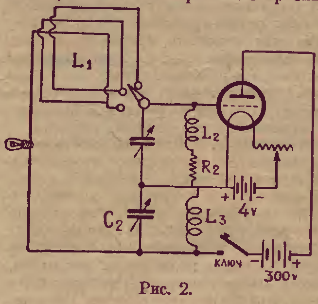
R2- 10.000 Ohm. Figure 2 shows simplified version of transmitter with frame antenna. Tap is taken
from the middle of the loop. The transmitter is tuned to the needed
frequency just with help of capacitor C1. The transmitters with the frame antennas has
small sizes, easy to hide and has directivity in transmission
that is useful in military application. At the TX there were used Russian tubes UT- 1, R-5. |
|
|
Figure 1 Transmitter with Frame Antenna with capacity adjustment |
 Figure 2 Simplified Version of Transmitter with Frame
Antenna |
|
|
|
|
|
|
|
||
|
|
|
|
|
|
Page- 58 |
|


58
 |
 |
 |
 |
Just for Fun:

Powered byIP2Location.com
Thanks for your time!
Last Updated:
January 19, 2020 21:46