


|
|
 |
 |
 |
|
|
Antentop is FREE e-magazine devoted to Antennas and Amateur Radio an
Special page devoted to
2xGU50 and 3xGU50 PA from UA1TAT

Custom Search
|
|
ANTENTOP-
01- 2008, # 010 |
2xGU50
and 3xGU50 PA from UA1TAT |
||
|
|
|
|||
|
|
|
|||
|
|
|
|||
|
|
2xGU50 PA The
PA was designed and then made (in several samples) by Yaroslav
Zhukov, UA1TAT. It is a "classical"
Tubes PA with grounded first grid. However, the feature of the
PA is the individual bias for the first grid of each of the used
tubes. It allows use tubes with slight different anode/grid characteristics. |
Yaroslav Zhukov, UA1TAT Credit Line: http://hamnv.narod.ru/2gu50.htm Credit Line: http://hamnv.narod.ru/3gu50.htm |
||
|
|
Figure
1 shows the schematic. Third grid of both tubes is grounded. Second grids of the both tubes
are connected to 250-V voltage stabilizer. The PA was designed for CB-station for 27-MHz. It is defined the
input circuit that provides good matching at the band. 3xGU50 PA The PA is made
on the base of 2xGU50 PA. Output power
of the 3xGU50 PA is 180- 200 Wtts. The
PA was designed for 160, 80, 40 and 20 meters. Input circuit is
broadband and can match the PA in wide frequencies range. The
input circuit is described at Antentop-
1-2008, p.62. Figure 2
shows the schematic of the 3xGU50 PA P.S. My thanks to Sergey Mironov
for the help during design, manufacturing and tuning of the PA. |
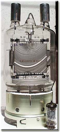
GU81M- Made in the |
||
|
|
|
|||
|
|
 |
|||
|
|
|
|||
|
|
|
Page 54 |
||

 |
 |
 |
 |
Just for Fun:

Powered byIP2Location.com
Thanks for your time!
Last Updated:
February 3, 2020 21:55