


|
|
 |
 |
 |
|
|
Antentop is FREE e-magazine devoted to Antennas and Amateur Radio an
Special page devoted to
Delta Loop UN7CI for 7, 10, 14 and 21- MHz

Custom Search
|
ANTENTOP-
01- 2008, # 010 |
Delta |
|
|
|
|
|
|
|
|
By:
Boris Popov (UN7CI),
Credit Line: www.cqham.ru |
|
The antenna was designed to work from a field conditions
at amateur's bands 7, 10, 14 and 21-MHz. The antenna has SWR less
the 2.0:1.0 at height of the lower side 1.2 meters above the ground.
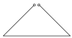
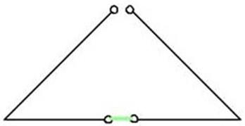
Antenna has good efficiency. At band 14-MHz the antenna is working like a full-
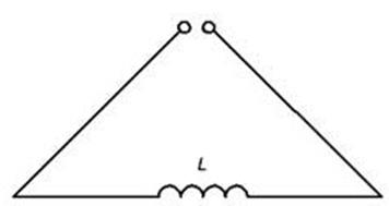
sized Delta Loop (Figure 1). At band 10-MHz the antenna is working
like an electrically lengthened (with inductor) Delta Loop (Figure 2).
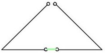
At band 7-MHz the antenna is working like a lambda/2 I.V. (Figure 3).
At band 21-MHz the antenna is working like a 3lambda/2 I.V. (Figure 4).
Figure
1. Full sized Delta Loop for 14-MHz
Figure
2. Electrically Lengthened Delta
Figure
3. Lambda/2- I.V. for 7-MHz |
Figure
4. 3 Lambda/2 I.V. for 21-MHz So, on the base a Delta Loop with perimeter
20 meters (or I.V. having two 10 meters wire) it is possible to
do a four band antenna. Figure
5 shows the design of the antenna. If the antenna is used for a field operation
and the middle of the antenna is accessible it is possible to
switch operation band with help of any suitable manual switch.
Off course, it is possible to use RF- relays to choose the band.
Inductor L contains 20 turns of insulated wire in diameter of
1.5-mm (15-AWG), coiled turn to turn on diameter 50- mm. Tuning Step
1: Antenna is installed at working position. Band Switch
is installed at position "3"- 14-MHz. RF signal (14.150-MHz)
is sent to the antenna. Antenna is tuned to resonance with help
of length A and B. Step
2: Band Switch is installed in position "1"-
10-MHz. RF signal (10.12-MHz) is sent to the antenna. Antenna
is tuned to resonance with help of inductor L. After the antenna is tuned to the 14-
and 10-MHz matching at bands 7- and 21-MHz should be reached without
any additional tuning of the antenna. 73! de UN7CI |
|
|
|
|
|
Page 33 |

33 34
 |
 |
 |
 |
Just for Fun:

Powered byIP2Location.com
Thanks for your time!
Last Updated:
February 2, 2020 22:41