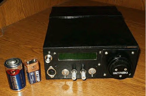
Receiver. DA1 is mixer. Quartz filter is a "3- quartz
filter." I am not to do selection of quartz for using it
in the filter (of course, if you have possibility to do the
selection- do it). All forms for coils are from old ex- USSR
VHF FM Transceiver "Len."
|
DA2 is used as a CW detector
and oscillator on 10700 kHz.. The frequency of generation is lowered up to required with the help
of RFC and L switched in serial. Audio amplifier, which is shown
on Figure 3, is implemented with a low
noise transistor and LM386N.
|
Transmitter: L5 (3 turn)/L6 (10 turn) are coiled on a ferrite
ring, international analog FT- 37-63, by 0.3 mm wire (28 AWG).
Each coil is sitting on its half of the ring. L3 5 turns wire
in 0.5 mm or 24 AWG) is coiled on a form in diameter of 7 mm.
VFO:
Figure 4 shows the VFO. This one is borrowed by me from "DC Receiver for
the 20 meters" by B. Stepanov,
(RU3AX). However I added a frequencies shift (VT2). This one
needed for SSB/CW QSO. VFO coil is wound on a ceramic form in
diameter of 10 mm and contained 45 turns. All capacitors are
high quality ones.
Electronic
switch: Figure 5 shows the Switch. Borrowed from Ukraine radio magazine "Radio-
Hobby" # 1, 2000.
PSB: I did not design a PSB for
the transceiver. I did it by "ugly" montage. Each
block is mounted on the own board. Fully assembled and tuned
boards are soldered at corners to transceiver case.
Adjustment and Tuning: Nothing special at tuning the unit. Do adjustment from Audio Amplifier,
then Receiver and Transmitter.
Commentary
to VFO Board:
KT315, KT361- Low Power RF Transistor,
250 MHz,
300 mW
KP303E: Low Power
RF FET Transistor
VD1: Zener Diode, 5V
VD2: Varicap, 10- 30 pF
|
Commentary to Main Board:
174PC1 = NE602,
NE612
KD510 = High
Speed RF Switch Diode
KT606 = RF Power
Transistor, 300 MHz, 1 W
KT922B- RF Power Transistor, 300 MHz, 10 W
KP303E: Low Power
RF FET Transistor
0B= 0 V
12 B= 12 V
Commentary to Switch Board:
KT209: 400 mW Switch Transistor
D311: Germanium Diode
Transceiver Mosquito 20m

|


