


|
|
 |
 |
 |
|
|
Antentop is FREE e-magazine devoted to Antennas and Amateur Radio an
Special page devoted to
Window Dipole Antennas with Capacitive Loads

Custom Search
|
ANTENTOP- 01- 2005, # 007 |
Window Dipole Antennas with Capacitive Loads |
||
|
|
|||
|
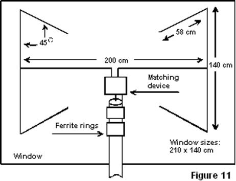
Figure
11 A window dipole antenna with capacitive loads of central
installation |
|||
|
Adjustment
of the both antennas is simple. A SWR- meter or HF- bridge (see
References [1])
is connected to feed points of the tuned antenna. Gradually shorten
moustaches (symmetrically each moustache) of the antenna to minimum
SWR or when antenna input impedance is just active (have no reactance)
at needed frequency. At shortening moustaches the moustache wires
roll up to a little coil. Input Impedance
of
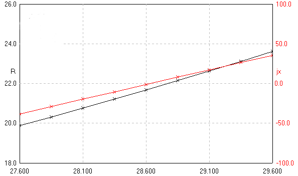
10-meters Band Window Dipole Antennas with Capacitive Loads Theoretical
parameters of the antennas (copper, wire in 1-mm (18- AWG) diameter) were simulated with the help of MMANA. Figure 13 shows input impedance of the antenna
shown in Figure
11. Theoretical input impedance of the antenna is 22-
Ohms. Practically measured input impedance of the antenna was
30- Ohms. Losses in neighbor objects add the 8 Ohms. Theoretical
gain for the antennas is near 1,5- 1,7 dBi. |
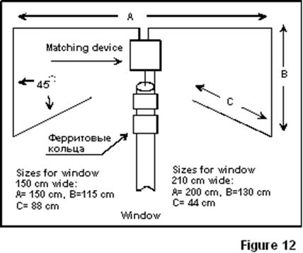
Figure 12 A window dipole antenna with capacitive loads of up or down installation |
||
|
Figure 13 Input impedance of the antenna shown in Figure 11 |
|||
|
|
Page 55 |
||
 |
 |
 |
 |
Just for Fun:

Powered byIP2Location.com
Thanks for your time!
Last Updated:
February 22, 2020 21:09