|  
                 
              Dummy 
                Load from Uwe, DJ8WX 
                
              0482183881-0001@t-online.de 
                 
                Here are two dummy loads in use; one is a bulb 110V/DC500W, Z 
                35 Ohm on 136kHz (bridge measurement) and the other is made of 
                four hollow ceramic resistors 200 Ohm/60W each, makes 200W only 
                (see Picture). but blowing air through the resistors (see attachment) 
                makes a lukewarm 300W dummy on 136kHz (0,4uH only). I tried 800W. 
                A peace of paper above the dummy caught fire within 10 sec. 
                 
                regards 
                Uwe/dj8wx 
                
              Dummy 
                Load from Ha- Jo, DJ1ZB 
                
              hajo.brandt.dj1zb@t-online.de 
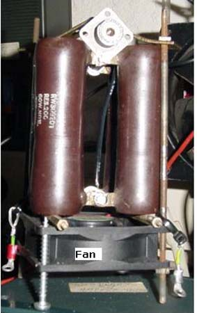
               
                For the time being I am using a dummy load made of ten low inductivity 
                DALE resistors Type NH-50, 499 ohms each, in parallel on a large 
                aluminum cooler (the fins of which could even be immersed into 
                water when necessary), which could be used up to 30 MHz with a 
                coil/capacitor matching arrangement at the input resulting in 
                an VSWR of about 1,2. The matching arrangement has been designed 
                about ten years ago in my qrl by measuring R and X of the parallel 
                resistor arrangement over the frequency range and trying to find 
                a suitable match by employing the old Supercompact software or 
                the ARRL Radio Designer. 
                 
                 
             | 
             
                 
              DJ8WX 
                Dummy Load 


             | 
          
           
            |  
               Therefore 
                I guess (I have not tried it yet, no need to do so) for such a 
                small band like 136 kHz it should be possible to build a dummy 
                load using ordinary wirewound resistors (preferably DALE or similars 
                because of their easy mounting on a cooler surface) because their 
                inductance could be cancelled by a suitable capacitance in parallel, 
                or by several distributed capacitors within the parallel resistor 
                arrangement. It should be rather simple to determine the capacitance 
                needed, a VSWR meter designed for LF should do it.  
                
              Caution: 
                Nobody should respect such a load to also absorb harmonics of 
                the transmitter frequency, because it is a tuned load. Harmonics 
                may see a short circuit, depending of the Q of the load, and will 
                be reflected. This special behaviour of the tuned load does not 
                matter, of course, if a low-pass filter is added to the tank circuit 
                of  the transmitter.  
                 
                73 Ha-Jo, DJ1ZB 
             | 
             
               Dummy 
                Load from John, G3PAI 
                
              About 
                30 years ago, Ongar Radio station to the north-east of London 
                had a number of nine kilowatt HF ISB transmitters. For dummy loads 
                they used carbon tubes about a foot long and an inch or two in 
                diameter. Resistance was 75 ohms and they were cooled by pumping 
                water through them. I had a box of such resistors, but they went 
                missing in a house move. 
                 
                73 
                John Rabson G3PAI 
                
              All 
                of these Dummy Loads were described at LF-Forum: 
                
              rsgb_lf_group@blacksheep.org 
                
                
             |